The specification says double suction pump. What has actually been selected? Although the label describes how liquid enters the impeller, it leaves the buyer to establish how the casing opens, how the assembly will sit in the room, which suction conditions it requires and where it can operate while meeting the project’s intended duty.
For a technical buyer, separating those questions makes competing proposals easier to understand. Horizontal split case and vertical split case options describe arrangements that need drawings; wear rings belong to the internal component specification. Flow, head and suction performance need their own evidence. Confusing these categories turns a useful product description into a claim it cannot support.
Double suction describes the impeller’s inlet arrangement
In a double-suction arrangement, liquid reaches the impeller from opposite sides. BBP’s split case product page describes this inlet configuration alongside its pump range. The description tells a reader something about the hydraulic layout, but it does not establish an efficiency advantage over every single-suction alternative or a particular suction requirement.
Begin with a sectional drawing. Follow the inlet passages to the impeller, distinguishing them from the external suction nozzle so that an internal flow description does not accidentally become a requirement for the building to provide separate external suction connections to each side of the rotating assembly. Check the nozzle arrangement itself. Keep the selected assembly drawing.
The label contains no duty point. A project still needs a flow requirement, total head, liquid description and operating range. Any comparison of efficiency or suction behavior must refer to the offered models under stated conditions, rather than treating the inlet arrangement as a universal ranking.
Split case answers a different question
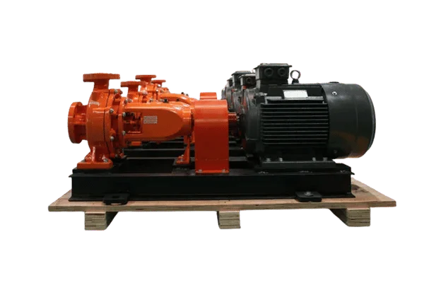
Split case describes the casing construction. For the axially split layout on the product page, the joint follows the shaft centerline and permits the casing to open for internal access. Double suction describes the impeller inlet. These descriptions can apply to the same pump, but they are not interchangeable definitions.
Separate construction from hydraulics. While the construction record identifies the casing split and access to the rotating assembly, the hydraulic record should identify the impeller arrangement and its matching performance curve, allowing the reviewer to check each description against the document that actually supports it. Wear rings and seals need a component list. Include materials and service requirements.
Opening a casing does not prove that every internal part can be replaced without disturbing surrounding equipment. Review the actual maintenance instructions and clearances. A photograph of a split case pump cannot establish the removal sequence for a different model or show whether its installed pipework blocks access.
Horizontal and vertical options need separate drawings
BBP describes a horizontal split case arrangement with the motor beside the pump and a vertical split case option with the motor above it. This is a useful distinction for layout review. It is not enough to compare a footprint rectangle while ignoring the height and the space needed during maintenance.
Compare the same room. Ask each bidder for an installation drawing and a maintenance envelope that show the casing lift and adjacent motor access for a horizontal arrangement, or overhead removal and access at different levels for a vertical arrangement, using the building’s actual handling constraints throughout. An outline drawing alone is insufficient. The removal route matters.
A claimed space saving has little meaning without an identified alternative and a defined measurement. Include access, removal routes and installed auxiliaries in the comparison. Choosing an orientation does not remove the need to check the hydraulic duty or the suitability of the proposed driver.
Read the curve as a description of one configuration
The Hydraulic Institute describes a pump performance curve as the head generated by a specific model across flow rates at a given speed. Efficiency, input power and required suction head add separate information. A headline maximum flow omits most of what a selection needs, including the head at that flow and the region where normal operation belongs.
Identify the speed and impeller diameter first. Once the curve is matched to the offer, locate the requested duty and examine the expected operating range alongside the input-power information, so the reviewer can see whether the proposed driver addresses the intended conditions rather than only a convenient point on the chart. Preserve the revision. Equipment changes can invalidate it.
A plotted line is not permission to operate anywhere along it. The manufacturer defines the allowable operating region, while the preferred region gives a narrower guide to favorable operation. Ask for those limits where they are missing, rather than inferring them from the edges of the chart.
Check suction conditions independently of the name
Available net positive suction head depends on the installation and the liquid’s vapor pressure. Required suction head comes from pump performance information at stated conditions. Suction-pipe losses, source level and temperature therefore belong in the assessment even when the impeller is described as double suction. The name does not supply missing site data.
According to the Hydraulic Institute, NPSH3 marks a 3 percent head reduction at constant flow when suction head is reduced. At that condition cavitation is already affecting performance. A selection needs an appropriate margin above the relevant requirement, considered together with the operating region.
Matching the available value to a catalog requirement is not a blanket reliability claim. Ask the designer and supplier to identify the limiting operating conditions and the margin basis. Keep the resulting calculation with the selected curve so later piping changes trigger a meaningful review.
Materials and replaceable parts need their own agreement
The BBP double-suction pump options include material choices and wear rings. Use those entries to establish which details need confirmation for the actual liquid and selected model. A range page is evidence that options are described, not a complete bill of materials for a particular purchase.
Request the wetted-part list. Identify the casing, impeller, wear rings and seal arrangement against the liquid chemistry and temperature supplied to the selector, retaining enough assembly detail for maintenance staff to distinguish the supplied parts from alternatives that share a familiar family name but are not interchangeable replacements. A model revision can matter. Keep the original identification.
A broad material label does not establish compatibility with every water treatment chemical or service condition. Obtain an application-specific recommendation where compatibility matters. Avoid treating the presence of a premium material option in a catalog as proof that the quoted unit includes it.
Adding another pump does not simply double system flow
Parallel pumping is another point where useful shorthand can mislead. The Hydraulic Institute explains that a combined parallel curve is formed by adding the pumps’ flows at the same head. The operating point then depends on where that combined curve meets the system curve. The installation, not just the pump count, decides the resulting flow.
For a station considering another double suction pump, compare the proposed stages of operation. Check normal demand with a single pump operating, the duty with additional pumps online, and the suction conditions associated with those states. A shared header does not make those operating points identical, and a high combined-flow figure says little about routine low-demand operation.
The combined curve does not prove that controls will stage pumps correctly. Include the operating sequence and permissible range in the review. Do not assume a parallel addition doubles delivery unless the system calculation supports that result.
Make the selection record answer the unresolved questions
A useful comparison ends with an identifiable configuration, not a collection of favorable descriptions. Put the requested duty beside the selected curve and list the operating limits. Add the installation drawing, liquid basis, driver selection and component schedule. Each document should describe the same proposed assembly.
Ask what changes if the duty, liquid temperature or room layout changes. A different speed may need a new performance review; a different orientation needs its own access check. Replacements for wear rings or seals need the correct assembly identification. These dependencies are easier to manage while proposals are still being compared.
A complete record does not certify the installation or guarantee service life. It does make the remaining decisions visible. Double suction then becomes a precise description within a checked selection, rather than a convenient phrase standing in for performance, maintenance and application suitability all at once.